Blynk is another way of sending and visualising data, from the Octopus, besides using Thingsspeak. To use Blynk, one needs to register with Blynk and download the Blynk app (available on iOS and Android).
Set up a remote sensing device on Blynk
To set up a data transmitting device on Blynk, one needs to do the following:
From the Blynk app : – Open the Blynk app on your smartphone. – Click on “new project”. – Choose “esp8266” for the “choose device” question. – Wait for the “Auth Token” email that Blynk has sent.
(then) In ArduBlocks : – In the Setup part of your ArduBlocks sketch, add aWLAN block and a Blynk-Cloud block. – In the WLAN block : specify the name of your wifi network and the password. – In the Blynk-Cloud block : the Copy the Auth Token from the Blynk email, and paste it into the API-Key part of the ArduBlocks Blynk-Cloud block.
As one might not always have an Octopus microcontroller at hand, people have asked me how to build a CO2Ampel – CO2 traffic light warning gadget – with a different microcontroller. Thankfully, such a device was recently assembled at Chaos Computer Club Freiburg.
To keep things inexpensive, we’re skipping the NeoPixel LED of the other tutorial, in this tutorial. Thus parts could be obtained for around 55 EUR. Later, we’ll cover how to connect the measuring device described here, to various displays . Also, those interested in finding further tips and information, can find more information in the Octopus section of this blog. (This post is for the most part identical with the CO2 Messen mit dem Octopus tutorial, also on this blog.)
Parts
I have provided links to the Mouser Onlineshop and to Tindie. You can also find the parts elsewhere, and my links aren’t affiliate links.
Node MCU (microcontroller, controlling the other elements ), via Amazon or Mouser.
CO2 sensor SCD30 – these are available with different interfaces. Eg. With a Grove connector – although often sold out – as well as without. In the case of the CO2 sensors without a grove connector, one needs to solder or otherwise connect it to the microcontroller. Slightly cumbersome but manageable. (Digikey from 53 EUR, RS Online from 72 EUR, Mouser around 50 EUR – at time of writing these were sold out, but new ones are orderd)
LCD panel – To display the data from the CO2 sensor. There are several variants, also with Grove connectors. From 6 EUR. from Mouser.
A power source – Likely you already have one – a USB charger. Just make sure you have a Micro-USB cable. Powerbanks are an alternative, especially if you want to carry the device around.
I2C Hub – a hub connecting several Grove connector cables. Grove connector cable – 2.5 EUR by Mouser.
A case – There are many ideas around. From Ikea picture frames, to Bird houses.
A Data ready USB cable – You probably have one at home, but may have to try several USB cables before you find one that can transmit data as well as power. Please note, quite often the USB cables one gets with various bits of electronics can only carry power. So it makes sense to try different USB cables if USB cable one doesn’t work.
Programming
To program Arduino code with visual programming (Ardu)blocks, we need to modify the Ardunio IDE code editor a bit. (For those that prefer text-code, you’ll find the produced Ardublocks code, in text form, at the end of this tutorial).
Windows: download the zip file with the ‘blocky’ Arduino IDE and then install the relevant hardware driver software. Install the Arduino into a very short File tree, et. C:/iotw. You may also have to take care if you have another Arduino Version already installed. Pay attention which do you start. Start by double clicking on the „IOTWerkstatt.bat“ file.
Mac OS: this is a bit more complicated compared to Windows, but accomplishable using these instructions (in German, again), or the ones below. Here too, you need to install the relevant hardware driver software, and download the special Arduino IDE. This is done as follows:
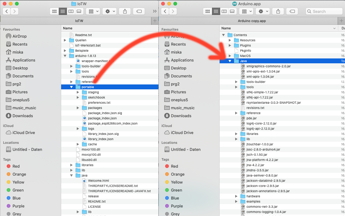
Following the installation of the Arduino IDE, right-click on the Arduino IDE icon, and select “Show package content” from the menu. This shows the files that make up the Arduino IDE.
Open the “Contents” folder of the just-opened Aruduino package.
Open the downloaded IoTW.zip file.
Drag the “Portable” folder (of the expanded IoTW.zip file ) into the “Java” folder of the expanded Arduino IDE files.
Now open the Arduino IDE.
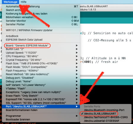
Open the “Tools” menu and go to Port submenu, and select “Dev/cu.SLAB_USBtoUART” option, to select the right port.
Open the “Tools” menu, as before, and now open the “Board” submenu, and select the “Generic ESP8266 Module”, as our board.
Cabling
The ESP9266 is cheap and can be used as the microcontroller for the CO2 Traffic lights.
Connect yellow on the D1, white on the D2, black on the GND, and red on the 3V. The cables connect with the Node MCU as shown in the table below. Now we need to solder them into place.
Node MCU pin
I2C / Grove Cable
3.3 V
red
GND
black
D1
yellow / SCL
D2
white / SDA
Here and now is a good time to solder the (Grove) cables to the Node MCU. Then we can do fun things like connect a Grove LCD and a SCD30 CO2 sensor to the Node NCU, via a I2C hub. As the grove Cables have preset colours, this should be simple.



Du muss angemeldet sein, um einen Kommentar zu veröffentlichen.