
This article is a variation on the tutorial explaining how to make a CO2 measuring device using a Octopus microcontroller, plus CO2 sensors and optional displays.
As one might not always have an Octopus microcontroller at hand, people have asked me how to build a CO2Ampel – CO2 traffic light warning gadget – with a different microcontroller. Thankfully, such a device was recently assembled at Chaos Computer Club Freiburg.
To keep things inexpensive, we’re skipping the NeoPixel LED of the other tutorial, in this tutorial. Thus parts could be obtained for around 55 EUR.
Later, we’ll cover how to connect the measuring device described here, to various displays . Also, those interested in finding further tips and information, can find more information in the Octopus section of this blog.
(This post is for the most part identical with the CO2 Messen mit dem Octopus tutorial, also on this blog.)
Parts
I have provided links to the Mouser Onlineshop and to Tindie. You can also find the parts elsewhere, and my links aren’t affiliate links.
- Node MCU (microcontroller, controlling the other elements ), via Amazon or Mouser.
- CO2 sensor SCD30 – these are available with different interfaces. Eg. With a Grove connector – although often sold out – as well as without. In the case of the CO2 sensors without a grove connector, one needs to solder or otherwise connect it to the microcontroller. Slightly cumbersome but manageable. (Digikey from 53 EUR, RS Online from 72 EUR, Mouser around 50 EUR – at time of writing these were sold out, but new ones are orderd)
- LCD panel – To display the data from the CO2 sensor. There are several variants, also with Grove connectors. From 6 EUR. from Mouser.
- A power source – Likely you already have one – a USB charger. Just make sure you have a Micro-USB cable. Powerbanks are an alternative, especially if you want to carry the device around.
- Grove connector cable – 2.5 EUR by Mouser.
- I2C Hub – a hub connecting several Grove connector cables. Grove connector cable – 2.5 EUR by Mouser.
- A case – There are many ideas around. From Ikea picture frames, to Bird houses.
- A Data ready USB cable – You probably have one at home, but may have to try several USB cables before you find one that can transmit data as well as power. Please note, quite often the USB cables one gets with various bits of electronics can only carry power. So it makes sense to try different USB cables if USB cable one doesn’t work.
Programming
To program Arduino code with visual programming (Ardu)blocks, we need to modify the Ardunio IDE code editor a bit. (For those that prefer text-code, you’ll find the produced Ardublocks code, in text form, at the end of this tutorial).
The easiest way to get going is to use a Windows PC and install the software following the instructions (including download links ) from the Umwelcampus Birkenfeld website. Instructions for MacOS and Raspberry PI can also be found, via the website’s overview page. I’ve also made some tutorials for Mac OS here on my blog. There is a (German language) Tutorial for Raspberry Pi, too.
Windows: download the zip file with the ‘blocky’ Arduino IDE and then install the relevant hardware driver software. Install the Arduino into a very short File tree, et. C:/iotw. You may also have to take care if you have another Arduino Version already installed. Pay attention which do you start. Start by double clicking on the „IOTWerkstatt.bat“ file.
Raspberry Pi: Setup RaspberryPi Os (Raspbibian) for your Pi and then download the modified Arduino IDE from here.
Mac OS: this is a bit more complicated compared to Windows, but accomplishable using these instructions (in German, again), or the ones below. Here too, you need to install the relevant hardware driver software, and download the special Arduino IDE. This is done as follows:
- Download the Driver.
- Download and install the Arduino IDE.
- Following the installation of the Arduino IDE, right-click on the Arduino IDE icon, and select “Show package content” from the menu. This shows the files that make up the Arduino IDE.
- Open the “Contents” folder of the just-opened Aruduino package.
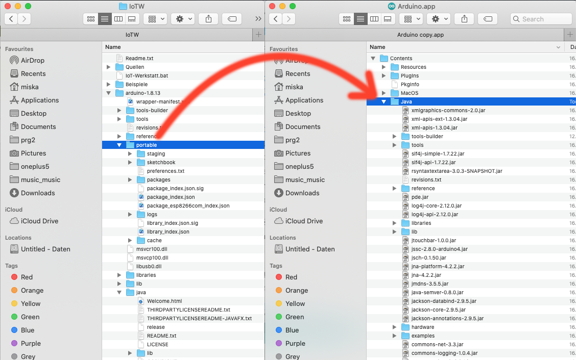
- Open the downloaded IoTW.zip file.
- Drag the “Portable” folder (of the expanded IoTW.zip file ) into the “Java” folder of the expanded Arduino IDE files.
- Now open the Arduino IDE.
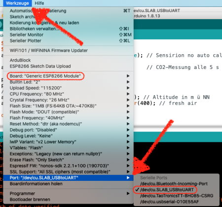
- Open the “Tools” menu and go to Port submenu, and select “Dev/cu.SLAB_USBtoUART” option, to select the right port.
- Open the “Tools” menu, as before, and now open the “Board” submenu, and select the “Generic ESP8266 Module”, as our board.
Cabling

Connect yellow on the D1, white on the D2, black on the GND, and red on the 3V. The cables connect with the Node MCU as shown in the table below. Now we need to solder them into place.
| Node MCU pin | I2C / Grove Cable |
| 3.3 V | red |
| GND | black |
| D1 | yellow / SCL |
| D2 | white / SDA |
Here and now is a good time to solder the (Grove) cables to the Node MCU.
Then we can do fun things like connect a Grove LCD and a SCD30 CO2 sensor to the Node NCU, via a I2C hub. As the grove Cables have preset colours, this should be simple.

We will have to solder the SCD30 to its own Grove cable as well.
| Sensor pin | Cable |
| VIN | red |
| GND (difficult to see) | black |
| SCL | yellow |
| RXSDA | white |
The Umweltwerkstatt Birkenfeld has assembled a good collection of relevant reflections, background and some instructions, for all this, on their website. (But its in German)
Complete the programming
Now there are two ways to programm the Microcontroller. You can use the Ardublock lego-style interface or use tect code. We have an example for text code below.

In the beginning we set the CO2 value as variabel. Then there is the display for the values. Below you find 4 what/if/then boxes. The first checks if the sensor does actually send a proper value. If it does not the Neopixel on the
At CCC Freiburg, we assembled some ready to use programme code.
Being assembled at the CCC, this code has some extra features. In addition to CO2 levels, temperature and relative humidity are also measured and displayed. A notification is also shown on the LCD display, when the CO2 concentration exceeds 900 ppm ( a quite high level of CO2 ).
There’s also code to send measurement data, using the MQTT protocol, over the Node MCU’s wifi. This might not be needed, but could prove quite useful and interesting. For instance, it allows one to monitor the CO2 levels of several sensor kits, and to do so from one’s smartphone or other net connected device. Thus one could monitor the CO2 levels in several rooms, and look at historical data to get an overview of CO2 concentrations over the course of eg a day. Check my tutorial on using Thingsspeak, to send_Octopus data, or my tutorial of how to send data from the NodeMCU to the Blynk app, using MTQQ.
Should ArduBlocks not used to program the code, one needs to make some small changes in the Arduino IDE :
- Open the Arduino IDE preferences.
In the field for ‘Additional Boards Manager URLs, insert the following link “http://arduino.esp8266.com/stable/package_esp8266com_index.json”.

- Now, in the Boards Manager menu, open the “Tools” menu, and open the “Boards Manager” in the “Boards” sub-menu.

- Search for the “Node MCU” ( also known as esp8266 ) entry and install the “ESP8266 Community” version driver of the board.
– Do make sure to select this board in Tools > Boards sub-menu. It’s the “Node MCU 1.0…” entry in the drop down menu.
Linux : one might need to add the user to the Dialout group, and log out and log in. - Now we need to add some libraries, using the Tools > Manage Library… menu option.


Install these libraries :
– WireData library, to send data using the I2C Grove connector hub (Wire.h).
– SparkFun SCD30 Arduino Library, to use the CO2 sensor (SparkFun_SCD30_Arduino_Library.h).
– Grove LCD library, to run the LCD display (rgb_lcd.h).
– Install the PubSubClient library (PubSubClient.h).
An here’s the Arduino (text) code:
/* This program is distributed in the hope that it will be useful,
 but WITHOUT ANY WARRANTY; without even the implied warranty of
 MERCHANTABILITY or FITNESS FOR A PARTICULAR PURPOSE.  See the
 GNU General Public License for more details. */


#include <ESP8266WiFi.h>
#include <PubSubClient.h>
#include <SparkFun_SCD30_Arduino_Library.h>
#include <Wire.h>
#include <rgb_lcd.h>

// ESP Wifi und PubSub Client sind für Wifi und Mqtt, sie werden nicht unbedingt gebraucht

String matrixausgabe_text  = " "; // Ausgabetext als globale Variable


volatile int matrixausgabe_index = 0;// aktuelle Position in Matrix


IPAddress myOwnIP; // ownIP for mDNS


//-------------- definition mqtt-object ueber WiFi
WiFiClient   espClient;
PubSubClient mqttclient(espClient);


//--------- list of mqtt callback functions
#define MAX_MQTT_SUB 10 // maximal 10 subscriptions erlaubt
typedef void (*mqtthandle) (byte*,unsigned int);
typedef struct {       // Typdeklaration Callback
  String topic;        // mqtt-topic
  mqtthandle fun;      // callback function
}
subscribe_type;
subscribe_type mqtt_sub[MAX_MQTT_SUB];
int mqtt_sub_count=0;


String MQTT_Rx_Payload = "" ;
//--------- mqtt callback function
void mqttcallback(char* to, byte* pay, unsigned int len) {
  String topic   = String(to);
  String payload = String((char*)pay);
  MQTT_Rx_Payload=payload.substring(0,len);
  Serial.println("\ncallback topic:" + topic + ", payload:" + MQTT_Rx_Payload);
  for (int i=0;i<mqtt_sub_count;i++) { // durchsuche alle subscriptions, bis topic passt
    if (topic==mqtt_sub[i].topic)
      mqtt_sub[i].fun(pay,len);         // Aufruf der richtigen callback-Funktion
  }
}


//------------ reconnect mqtt-client
void mqttreconnect() { // Loop until we're reconnected
  if (!mqttclient.connected()) {
    while (!mqttclient.connected()) {
      Serial.print("Attempting MQTT connection...");
      if (mqttclient.connect("StrandiCO2")) {
        Serial.println("connected");
        for (int i=0;i<mqtt_sub_count;i++) { // subscribe topic
          mqttclient.subscribe(mqtt_sub[i].topic.c_str());
          Serial.println("\nsubscribe");
          Serial.print(mqtt_sub[i].topic);
        }
      }
      else {
        Serial.print("failed, rc=");
        Serial.print(mqttclient.state());
        Serial.println(" try again in 5 seconds");
        delay(5000);
      }
    }
  }
  else {
    mqttclient.loop();
  }
}

//Initialwerte vom Program gesetzt
String alarm = "" ;
int hum = 99 ;
int tmp = 99 ;
int co2 = 9999 ;
//Reading CO2, humidity and temperature from the SCD30 By: Nathan Seidle SparkFun Electronics


//https://github.com/sparkfun/SparkFun_SCD30_Arduino_Library


SCD30 airSensorSCD30; // Objekt SDC30 Umweltsensor
//LCD RGB, 2013 Copyright (c) Seeed Technology Inc.   Author:Loovee
rgb_lcd lcd;


void setup(){ // Einmalige Initialisierung
  Serial.begin(115200);
  //----------------------------------MQTT-Client
  mqttclient.setServer("172.16.0.69", 1883);
  mqttclient.setCallback(mqttcallback);
//hier ändern wenn man einen anderen Server für MQTT hat

  Wire.begin(); // ---- Initialisiere den I2C-Bus


  if (Wire.status() != I2C_OK) Serial.println("Something wrong with I2C");


  if (airSensorSCD30.begin() == false) {
    Serial.println("The SCD30 did not respond. Please check wiring.");
    while(1) {
      yield();
      delay(1);
    }
  }


  airSensorSCD30.setAutoSelfCalibration(false); // Sensirion no auto calibration


  airSensorSCD30.setMeasurementInterval(2);     // CO2-Messung alle 5 s


  Serial.println();
  lcd.begin(16, 2);// LCD Backlight initialisieren


  //------------ WLAN initialisieren
//Wlan Name eintragen bei "my_wifi" und Passwort anstelle "topsecret" Anführungszeichen lassen!
  WiFi.persistent(false);
  WiFi.mode(WIFI_STA);
  delay(100);
  Serial.print ("\nWLAN connect to:");
  Serial.print("my_wifi");
  WiFi.begin("my_wifi","topsecret");
  while (WiFi.status() != WL_CONNECTED) { // Warte bis Verbindung steht
    delay(500);
    Serial.print(".");
  };
  Serial.println ("\nconnected, meine IP:"+ WiFi.localIP().toString());
  matrixausgabe_text = " Meine IP:" + WiFi.localIP().toString();
  myOwnIP = WiFi.localIP();
  matrixausgabe_index=0;


  Wire.setClock(100000L);            // 100 kHz SCD30
  Wire.setClockStretchLimit(200000L);// CO2-SCD30
}


void loop() { // Kontinuierliche Wiederholung
  delay(2000);
  co2 = airSensorSCD30.getCO2() ;
  tmp = airSensorSCD30.getTemperature();
  hum = airSensorSCD30.getHumidity();
  alarm = "      ";
  if (co2 > 900) alarm = "Alarm";
  Serial.print("co2 (ppm) : "+String(String(co2)));
  Serial.println();
  lcd.setCursor(0,0);
  lcd.print(String(String(String(co2)))+"ppm co2    ");
  lcd.setCursor(0,1);
  lcd.print(String(String(String(tmp))+"'C "+String(String(hum)))+"% "+String(String(alarm)));
  mqttreconnect();
  {
    String pay=String("CO2:_"+String(String(co2)));
    mqttclient.publish("CO2",pay.c_str());
    Serial.print("\nmqtt publish: ");
    Serial.print(pay);
  };
}
Du muss angemeldet sein, um einen Kommentar zu veröffentlichen.