Build your own Covid Stop Lights or Better Lüften like a German

While building your own Co2 Sensor and Warning Lights

More an more Germany are more and more concerned with Lüften. Lüften means to open the Windows of the room you are in and then venilate it properly. It’s done best, by opening two windows on walls opposing each other, thus letting air blow through.

Because Germans are masters in „Lüften“ and because many people wanted to know, how to build these little warning lights, in order to know when they should open the Windows and let fresh air in, I wrote a lot of articles on my blog. But these were all in German. So Miska Knapek translated one article into English and I did some editing.

During the Corona Crisis venting has become even more important. Corona spreads through droplets but also through aerosoles.  Since it’s considered very likely that aerosol can also be a carrier of the SARS-CoV-2 virus, in addition to exhaled (humidity) droplets, we need a way to measure them. However the problem is this:

Whereas the comparatively larger droplets fall to the ground relatively quickly, aerosol can stay in the air longer and may disperse and distribute itself within a closed space” (My translation of a Robert Koch Institute (RKI) statement (RKI is a  German Institute for disease control and prevention).

As aerosol is difficult to measure, but it roughly correlates with CO2 concentration in the air of an enclosed space, clever people like Guido Burger and the Umweltcampus Birkenfeld have devised a way to easily measure CO2 concentrations.

Building instructions for the  CO2 Ampel / CO2 Light, by Guido Burger, published in Make Magazine’s website (in German).

Fortunately, Sensirion makes a CO2 sensor and Guido Burger has ready to tinker microcontroller, the Octopus Board, which can interface and control the CO2 sensor. It is possible to use a Node MCU as well.

The microcontroller can be programmed using the ArduBlocks visual Arduino programming language. Of course you can still do text based programming, if you want it. See the ArduBlocks equivalent code towards the bottom of this article.

With ArduBlocks, using visual ‘programming blocks’, one can do the essential bits of a programming language – loops, conditional statements (if/then), and send/receive signals from various sensors, or send and receive data via MQTT, Thingsspeak or Blynk. (Sorry the Articles are in German, but you may use Google Translate)

The Campus Birkenfeld of Technische Hochschule Trier has more material about this CO2 measuring device, including relevant considerations, background, as well assembled a bit of a building instruction (but it’s all in German).
While I enjoy tinkering, in the end I was mostly interested in having a working measuring device. Thus I’ve assembled a quick assembly guide here, below.

Parts list

I have provided links to the Mouser Onlineshop and to Tindie. You may find the parts elsewhere and they are not affiliate links. 

  • Ocotopus Board – which you can get via Tindie. Even if it says it’s sold out, you can still try ordering one. In the worst case, send its inventor Guido Burger a message, to ask if they’re available. Ca. 30 EUR
  • CO2 sensor SCD30 – these are available with different interfaces. Eg. With a Grove connector – although often sold out – as well as without. In the case of the CO2 sensors without a grove connector, one needs to solder or otherwise connect it to the microcontroller. Slightly cumbersome but manageable. Ca. 45 EUR
  • Grove cabelconnecting straight to the Octopus Platine, one can use this to attach sensors, displays and other electronics with Grove interfaces. Ca. 3 EUR
  • LCD panel – To display the data from the CO2 sensor. There are several variants, also with Grove connectors. From 6 EUR. from Mouser.
  • A power source Likely you already have one – a USB charger. Just make sure you  have  a Micro-USB cable. Powerbanks are an alternative, especially if you want to carry the device around. 
  • A case There are many ideas around. From Ikea picture frames, to Bird houses.
  • A Data ready USB cable You probably have one at home, but may have to try several USB cables before you find one that can transmit data as well as power. Very often Electronics come with a cheap cable that can only carry power.

In total, this makes for ca 90 EUR in parts.

„Build your own Covid Stop Lights or Better Lüften like a German“ weiterlesen

CO2 Ampel Ideen

„Im Internet“ oder besser auf twitter erreichen mich immer wieder coole Ideen für die CO2 Ampel. Ein paar habe ich hier gesammelt, als Inspiration vielleicht für den Nachbau. Dieser Artikel wird ständig auf dem laufenden gehalten.

Hardware

Viele Leute haben gute Ideen für nette und sinnvolle Gehäuse.

Im Ikea Bilderrahmen, den gibt es für unter 5 EUR bei IKEA:

In einem netten Gehäuse. Vorne für die Kinder mit Neopixelring, jinten für die Lehrer mit LCD. Diese Bastelanleitung berueht übrigens auf dem Assembled Feather HUZZAH w/ ESP8266 und dem Seeestudio Grove-Shield, beide könnten ggf. etwas einfacher zu beschaffen sein als die Octopus Platine.

Im Google Kartong und mit TagoIO:

Nikolai Ruhe hat eine schöne große Ampel mit LED Streifen und ESP32. Die kann man kaum übersehen.

Software Ideen

„CO2 Ampel Ideen“ weiterlesen

CO2 messen mit Node MCU (falls man keinen Octopus zur Hand hat)

Nicht immer hat eine Octopus Platine zur Hand. Deshalb haben mich einige gefragt, wie man eine CO2 Ampel bzw. eine Meßgerät mit einer anderen Platine bauen kann. Im Chaos Computer Club hier in Freiburg wurde schließlich so eine Ampel gebaut. Wir haben hier – auch aus Kostengründen, diese Teile dürften etwa bei 55 EUR liegen – etwa auf eine NeoPixel LED verzichtet. Später wird es hier Tipps geben, wie man dieses Meßgerät mit anderen Ausgabegeräten verbinden kann. Wer aber dazu noch Tipps sucht, dem seien die anderen Artikel zum Thema Ocotopus auf dem Blog angeraten. Dieser Post ist in Teilen identisch mit der Anleitung CO2 Messen mit dem Octopus.

Teile

  • Node MCU (Platine die steuert) (bei Amazon, bei Mouser)
  • SCD30 (CO2 Sensor) (Digikey ab 53 EUR inklusive Mwst, RS Online ab 72 EUR mit MwSt, bei Mouser derzeit ausverkauft)
  • Grove LCD Display (bei Mouser)
  • I2C Hub (für die Bequemlichkeit, bei Mouser)
  • Kabel (es reicht eine Packung, bei Mouser)
  • USB Kabel (zur Stromversorgung und zum flashen)
  • Stromversorgung, entweder Powerbank oder Handyladegerät

Programmcode

Hier gibt es zunächst eine Anleitung, eigenen Code mithilfe der Ardublock Software zu schreiben bzw. zusammen zu klicken, wer das nicht will und einfach mit der Arduino IDE Code reinkopieren, der findet unten ein Beispiel mit einer Anleitung.

ein ganz einfacher Code im Ardublockly, der aber alles zeigt was wir zum Meßen brauchen.

Am einfachsten verwendet man ein Windows PC und installiert es sich nach Anleitung (mit Downloadlinks) auf der Website vom Umweltcampus Birkenfeld. Auf der Übersichtsseite zum Projekt Octopus finden sich auf die Anleitungen für Pi und MacOs. Ich habe für MacOs auch eine Anleitung auf diesem Blog.

Für Windows ist es relativ einfach, download des aktuellen Zip-File der Werkstatt-Plattform und dann den Chipsatz Treiber installieren. Wie es geht haben sie in einem PDF erklärt. Wichtig ist unter Werkzeuge den richtigen „Com“ Port auszuwählen.

Für MacOS ist es ein wenig komplizierter, aber mit der Anleitung auch gut zu machen. Auch hier den Chipsatz Treiber installieren, die Arduino IDE von Arduino herunterladen, dann installieren. Dann in den Ordner Programme gehen, dort rechtsklick und „Paketinhalt zeigen“ auswählen. Wir sehen dann was sich hinter dem Icon verbrigt, nämlich die Struktur des Arduino Programms. Jetzt das Archiv „IoTW.zip“ herunterladen, dann entpacken und öffnen. Da gibt es ein Unterordner namens „Portable“, diesen nehmen und in die auf dem Mac installiere Arduino IDE und da in den Unterordner „Java“ ziehen.

Noch sind wir nicht ganz fertig, wir gehen noch unter „Werkzeuge“ auf „Boardverwalter“, da gibt es ganz viele Boards. Wir gehen auf „ESP Community“ Package und führen ggf. eine Update durch.

Bei „Werkzeuge“ wählen wir noch unter Port: „/dev/cu.SLAB…“ aus. Als Board stellen wir „Generic ESP8266 Module“ ein. Mehr müßen wir nicht einstellen.

Sollte etwas beim flashen der Software auf das Board nicht klappen, vielleicht mal ein anderes USB Kabel verwenden.

Verkabelung

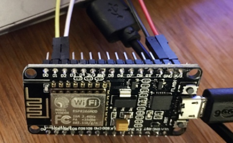
Gelb an D1, Weiß an D2, Schwarz an GND und Rot and 3V.

Wir verkabeln an den Node MCU wie folgt und löten dann ggf.:

Node MCU BeinchenI2C / Grove Kabel
3,3 Vrot
GNDschwarz
D1gelb / SCL
D2weiß / SDA

Hier können wir die Kabel auch schon an den Node MCU anlöten. Danach stecken wir auf dem I2C Hub sowohl das Kabel an das Grove LCD Display als auch an den SCD 30 CO2 Sensor.

Auch hier werden wir löten müßen.
SensorKabel
VINrot
GND (schlecht zu lesen)schwarz
SCLgelb
RXSDAweiß
Verkabelungsschema

Die Umweltwerkstatt Birkenfeld hat die Überlegungen, Hintergründe und ein wenig eine Anleitung auch auf ihrer Website zusamemngefasst.

„CO2 messen mit Node MCU (falls man keinen Octopus zur Hand hat)“ weiterlesen