


More an more Germany are more and more concerned with Lüften. Lüften means to open the Windows of the room you are in and then venilate it properly. It’s done best, by opening two windows on walls opposing each other, thus letting air blow through.
Because Germans are masters in „Lüften“ and because many people wanted to know, how to build these little warning lights, in order to know when they should open the Windows and let fresh air in, I wrote a lot of articles on my blog. But these were all in German. So Miska Knapek translated one article into English and I did some editing.
During the Corona Crisis venting has become even more important. Corona spreads through droplets but also through aerosoles. Since it’s considered very likely that aerosol can also be a carrier of the SARS-CoV-2 virus, in addition to exhaled (humidity) droplets, we need a way to measure them. However the problem is this:
“Whereas the comparatively larger droplets fall to the ground relatively quickly, aerosol can stay in the air longer and may disperse and distribute itself within a closed space” (My translation of a Robert Koch Institute (RKI) statement (RKI is a German Institute for disease control and prevention).
As aerosol is difficult to measure, but it roughly correlates with CO2 concentration in the air of an enclosed space, clever people like Guido Burger and the Umweltcampus Birkenfeld have devised a way to easily measure CO2 concentrations.
Fortunately, Sensirion makes a CO2 sensor and Guido Burger has ready to tinker microcontroller, the Octopus Board, which can interface and control the CO2 sensor. It is possible to use a Node MCU as well.
The microcontroller can be programmed using the ArduBlocks visual Arduino programming language. Of course you can still do text based programming, if you want it. See the ArduBlocks equivalent code towards the bottom of this article.
With ArduBlocks, using visual ‘programming blocks’, one can do the essential bits of a programming language – loops, conditional statements (if/then), and send/receive signals from various sensors, or send and receive data via MQTT, Thingsspeak or Blynk. (Sorry the Articles are in German, but you may use Google Translate)
The Campus Birkenfeld of Technische Hochschule Trier has more material about this CO2 measuring device, including relevant considerations, background, as well assembled a bit of a building instruction (but it’s all in German).
While I enjoy tinkering, in the end I was mostly interested in having a working measuring device. Thus I’ve assembled a quick assembly guide here, below.
Parts list
I have provided links to the Mouser Onlineshop and to Tindie. You may find the parts elsewhere and they are not affiliate links.
- Ocotopus Board – which you can get via Tindie. Even if it says it’s sold out, you can still try ordering one. In the worst case, send its inventor Guido Burger a message, to ask if they’re available. Ca. 30 EUR
- CO2 sensor SCD30 – these are available with different interfaces. Eg. With a Grove connector – although often sold out – as well as without. In the case of the CO2 sensors without a grove connector, one needs to solder or otherwise connect it to the microcontroller. Slightly cumbersome but manageable. Ca. 45 EUR
- Grove cabel – connecting straight to the Octopus Platine, one can use this to attach sensors, displays and other electronics with Grove interfaces. Ca. 3 EUR
- LCD panel – To display the data from the CO2 sensor. There are several variants, also with Grove connectors. From 6 EUR. from Mouser.
- A power source – Likely you already have one – a USB charger. Just make sure you have a Micro-USB cable. Powerbanks are an alternative, especially if you want to carry the device around.
- A case – There are many ideas around. From Ikea picture frames, to Bird houses.
- A Data ready USB cable – You probably have one at home, but may have to try several USB cables before you find one that can transmit data as well as power. Very often Electronics come with a cheap cable that can only carry power.
In total, this makes for ca 90 EUR in parts.
Assembly: Install the software
To program Arduino code with visual programming blocks – to control the Octopus, the sensor and see the CO2 measurements – we need to modify the Ardunio IDE code editor a bit. There is an english Quick Start on their Website (PDF) but you can follow the instructions here, too.
Windows: download the zip file with the ‘blocky’ Arduino IDE and then install the relevant hardware driver software. Install the Arduino into a very short File tree, et. C:/iotw. You may also have to take care if you have another Arduino Version already installed. Pay attention which do you start. Start by double clicking on the „IOTWerkstatt.bat“ file.

Don’t forget to select the right ‘Com’ port, in the Tools menu of the Arduino IDE. Also select „Generic ESP8266“ in the Tools/Boards Dropdownmenu.
Mac OS: this is a bit more complicated compared to Windows, but accomplishable using these instructions (in German, again). Here too, you need to install the relevant hardware driver software, and download the special Arduino IDE. This is done as follows:
- Download the Driver.
- Download and install the Arduino IDE.
- Following the installation of the Arduino IDE, right-click on the Arduino IDE icon, and select “Show package content” from the menu. This shows the files that make up the Arduino IDE.
- Open the “Contents” folder of the just-opened Aruduino package.
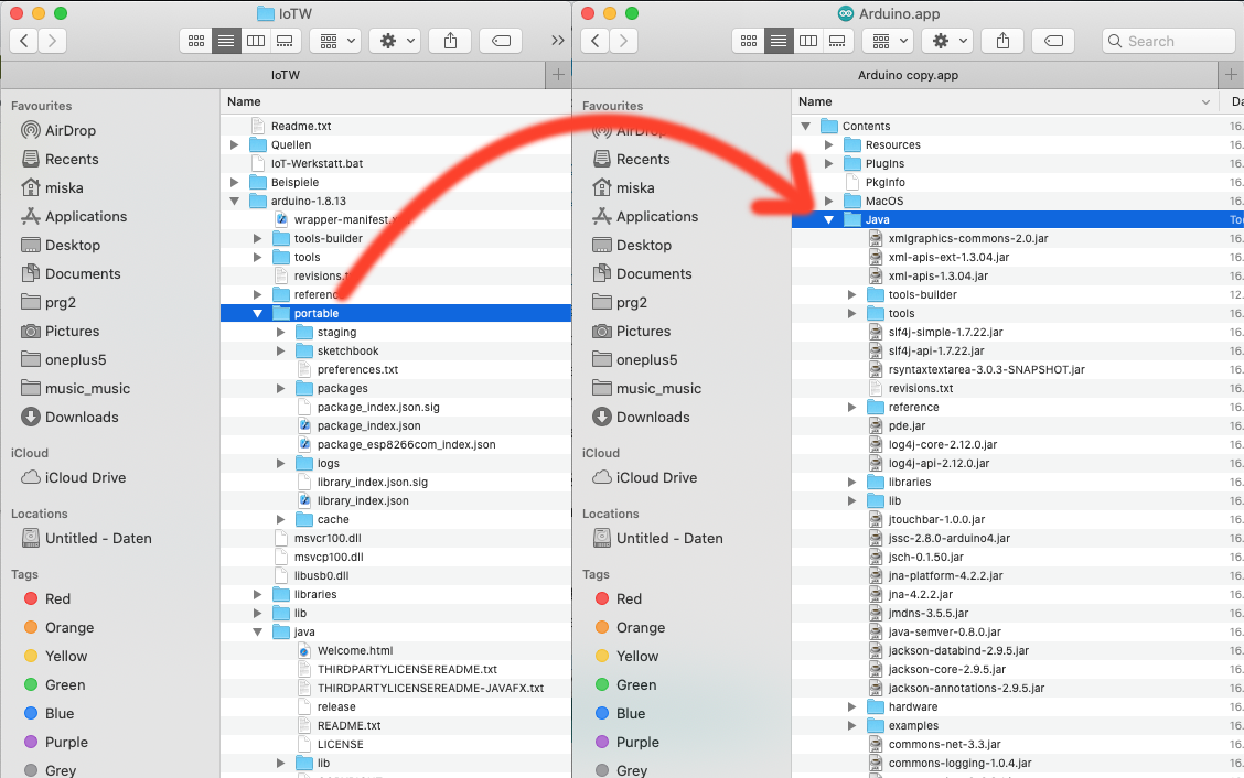
- Open the downloaded IoTW.zip file.
- Drag the “Portable” folder (of the expanded IoTW.zip file ) into the “Java” folder of the expanded Arduino IDE files.

- Now open the Arduino IDE.
- Open the “Tools” menu and go to Port submenu, and select “Dev/cu.SLAB_USBtoUART” option, to select the right port.
- Open the “Tools” menu, as before, and now open the “Board” submenu, and select the “Generic ESP8266 Module”, as our board.
Hardware assembly

To connect a SD30 Sensor with a Grove connector, a bit of soldering is required. It’s easier than it sounds.

First, remove the white plastic connector at the end of a Grove cable, and solder the wires straight onto the pins of the SD20 Sensor, according to the guide below:
Sensor Pin to Cable (colour)
| Sensor | Cabel |
|---|---|
| VIN | red |
| GND | black |
| SCL | yellow |
| RXSDA | white |
“Program” the Octopus software
Now we’re almost done!
We just need to ‘tell’ the Octopus what it should do. For this we can use a pre-assembled ArduBlocks block assembly. (The Arduino source code for this is published further below in the article).

My ArduBlocks program for the sensor. It asks for and receives new sensor data every five seconds. However, at this stage the code doesn’t include any extra functionality, like a CO2 level warning, or the activation of a connected light.

Moving a step up in complexity – my programme for running the CO2 sensor and an external light display. It basically consists of two main parts:
Setup – this is where one ‘starts up’, or initialises, all the things the Octopus should do.
Loop – This is what is to happen continuously. In our case, this means, every 5000 milliseconds (5 seconds), show the current CO2 sensor value at the Grove LCD Display. Below it is a sample sketch for a green, yellow, red Traffic Light System.
Values for the Traffic Lights
For the Traffic Lights Warning System I have choosen these values:
0 – 700 ppm = green. According to the German Enviromental Authority this is the CO2 concentration, that you should aim for.
700 – 1000 = yellow. This is when you should start opening the window.
Above 1000 ppm = red. You should go and open the Window.
Notable details in the ArduBlocks interface
Control structure ( leftmost part of the interface).

You find all the stuff on the left. The control structures such as loop, if/then or if/then-else are below the yellow button.

In the leftmost panel, containing the control elements, there’s a block representing “wait”. Positioning this on the ArduBlocks “programme surface” creates a wait period of one’s choosing.

In the leftmost panel, under “external interfaces” one can find a block which is very useful, it allows one to control the 7-Segment Display.

There’s, naturally, also a block for controlling the CO2 Sensor.

One can also connect the blocks, such that the Grove LCD Display that shows the sensor’s value. As the CO2 sensor also measures relative humidity and temperature, one can choose to display these as well. You find the „glue“ block in the „Communication M2M“ box.

Ok, enough text, let’s go ahead and experiment.
Code

/* This program is distributed in the hope that it will be useful,
but WITHOUT ANY WARRANTY; without even the implied warranty of
MERCHANTABILITY or FITNESS FOR A PARTICULAR PURPOSE. See the
GNU General Public License for more details. */

#include <SparkFun_SCD30_Arduino_Library.h>
#include <Wire.h>
#include <rgb_lcd.h>

int co2 = 0 ;
//Reading CO2, humidity and temperature from the SCD30 By: Nathan Seidle SparkFun Electronics

//https://github.com/sparkfun/SparkFun_SCD30_Arduino_Library

SCD30 airSensorSCD30; // Objekt SDC30 Umweltsensor
//LCD RGB, 2013 Copyright (c) Seeed Technology Inc. Author:Loovee
rgb_lcd lcd;


void setup(){ // Einmalige Initialisierung
Wire.begin(); // ---- Initialisiere den I2C-Bus

if (Wire.status() != I2C_OK) Serial.println("Something wrong with I2C");

if (airSensorSCD30.begin() == false) {
Serial.println("The SCD30 did not respond. Please check wiring.");
while(1) {
yield();
delay(1);
}
}

airSensorSCD30.setAutoSelfCalibration(false); // Sensirion no auto calibration

airSensorSCD30.setMeasurementInterval(2); // CO2-Messung alle 5 s

Serial.begin(115200);
lcd.begin(16, 2);// LCD Backlight initialisieren

Serial.println();
Wire.setClock(100000L); // 100 kHz SCD30
Wire.setClockStretchLimit(200000L);// CO2-SCD30
}

void loop() { // Kontinuierliche Wiederholung
co2 = airSensorSCD30.getCO2() ;
lcd.setCursor(0,0);
lcd.print(String("CO2:"+String(String(co2)))+" ");
Serial.print("CO2:"+String(String(co2)));
Serial.println();
}
Du muss angemeldet sein, um einen Kommentar zu veröffentlichen.